Creating Rainbow using Vix 🌈
This is a blog version of the Livebook. You can try the interactive version here
![]()
Mix.install([
  {:vix, "~> 0.17.0"},
  {:kino, "~> 0.9.1"}
])
Introduction
Libvips provides over 300 image processing operations, but getting the intuition behind what is possible and how to combine the primitive image processing operations can be a challenging.
With this notebook we look into some and of the core operations while trying to achieve a simple goal, which is to generate a rainbow 🌈. Rainbow should have the half-circular arch, there should be a smooth blend between the colors.
Generating the colors
First let’s look into just generating the rainbow colors. We need to generate the whole spectrum with the smooth blend between them.
libvips provides buildlut function which generate a pointwise
intermediate values between the provided points. lut here means
Look Up Table. buildlut takes a 1D matrix where each value
represent different points of the format [position, bands] and
buildlut will build a single band, one pixel height image with a
smooth poitwise transition between the points. If you pass [0, 0]
(at position zero pixel value is zero) [255, 255] (at position 255
value is 255), the buildlut will return an image with pixels 0 at
position 0, 1 at position 1, 2 at position 2 etc, ending with
255 at position 255. We can think of it as range 0..255.
alias Vix.Vips.Image
alias Vix.Vips.Operation

# buildlut needs matrix image.
# we can create matrix-image using `Image.new_matrix_from_array` which takes
# list and return an vips-image which can be passed to buildlut
{:ok, mat} = Image.new_matrix_from_array(2, 2, [[0, 0], [255, 255]])

gradient = Operation.buildlut!(mat)

We can see the gradient clearly if we increase the image height
Operation.resize!(gradient, 3, vscale: 50)

buildlut accepts multiple bands as well. So we can generate gradient
for colors too, not just between black and white
defmodule Vix.KinoUtils do
  # Utility to read color and parse hex string into list of
  # 8-bit integers.
  def read_colors do
    start_color = Kino.Input.color("Start", default: "#DDDD55")
    end_color = Kino.Input.color("End", default: "#FF2200")

    [start_color, end_color]
    |> Kino.Layout.grid(columns: 6)
    |> Kino.render()

    start_color = read(start_color)
    end_color = read(end_color)

    {start_color, end_color}
  end

  defp read(input) do
    "#" <> color = Kino.Input.read(input)

    for <<hex::binary-size(2) <- color>> do
      String.to_integer(hex, 16)
    end
  end
end

# read user input
{start_color, end_color} = Vix.KinoUtils.read_colors()

{:ok, mat} =
  Image.new_matrix_from_array(4, 2, [
    [0 | start_color],
    [255 | end_color]
  ])

mat
|> Operation.buildlut!()
|> Operation.cast!(:VIPS_FORMAT_UCHAR)
|> Operation.resize!(3, vscale: 50)

# change the `Start` and `End` colors and evaluate

To generate the rainbow colors, the pixel values in RGB colour space
will be [255, 0, 0] (red), [255, 165, 0] (orange) ... [143, 0, 255] (violet). We could generate these values but it is inconvenient to
juggle all 3 bands.
Generating the colors in HSV color space we need [0, 255, 255] (red), [24, 255, 255] (orange) ... [212, 255, 255] (violet). Which is much
nicer to work with, since we only need to change one value.
{:ok, mat} =
  Image.new_matrix_from_array(4, 2, [
    # position 0   - [0,   255, 255]
    [0, 0, 255, 255],
    # position 255 - [255, 255, 255]
    [255, 255, 255, 255]
  ])

gradient = Operation.buildlut!(mat)

# by default the colour space won't be HSV.
# We make a shallow copy and set the colorspace to HSV.
# While also setting band format to `unsigned char`
rainbow_colors =
  Operation.copy!(gradient,
    band_format: :VIPS_FORMAT_UCHAR,
    interpretation: :VIPS_INTERPRETATION_HSV
  )

# resize to make it visible
Operation.resize!(rainbow_colors, 3, vscale: 50)

# notice that the output spectrum starts from RED and ends with RED.
# this is slightly incorrect, since rainbow ends with violet. We'll fix this later

Generating the Arch
How to generate the half circular arch? there are several way to approach this but we are going to use complex band format and polar coordinates.
Complex Numbers
A pixel on the image has a position represented its x coordinate and y
coordinate. value x represent point position along the width and y
axis along the height, ie. we need 2 values to form a point. In
complex number system a pixel is a single complex number value. A
value in complex number system represents a point on a 2D plane
instead of a value on an axis. You can just think of it as just a
fancy way to represent position on 2D plane. Internally a complex
number is just a pair of Real part and Imaginary part.
There are two different ways to locate a point on 2D plane
- Cartesian coordinate system
- Polar coordinate system
Cartesian coordinate System
Here real part represent x coordinate and imaginary part represents y coordinate.
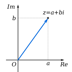
a and b is used to locate the point z
Polar System
Here real part represents distance from the origin and imaginary part represents angle
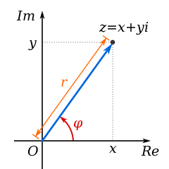
Angle φ and distance r is used to locate point z
But why do we need complex number?
Because it makes certain operations simple. Operations which operate on plane rather than axis. For example, to draw a circle on a polar plane we only need to vary angle keeping the distance constant.
Lets take an example and see libvips operations on complex planes. First let’s create a image at with its origin at the center of the image. It makes it easy to understand what is happening.
use Vix.Operator

width = height = 255

# create 200 x 200 matrix where each pixel represent its own position.
# pixel at left-top will be `{0, 0}` (black)
# pixel right-bottom will be `{255, 255}` (white)
xy = Operation.xyz!(width, height)

# Display how axis values are chaning
Kino.Layout.grid([Kino.Text.new("X-Axis"), Kino.Text.new("Y-Axis"), xy[0], xy[1]], columns: 2)
|> Kino.render()

# move origin to center of the image
xy = (xy - [width / 2, height / 2]) * 2

# Display how axis values are changing after moving the origin.
# Notice that origin black pixel starts at top-left before
# and at center after moving the origin
Kino.Layout.grid(
  [Kino.Text.new("Centered X-Axis"), Kino.Text.new("Centered Y-Axis"), xy[0], xy[1]],
  columns: 2
)
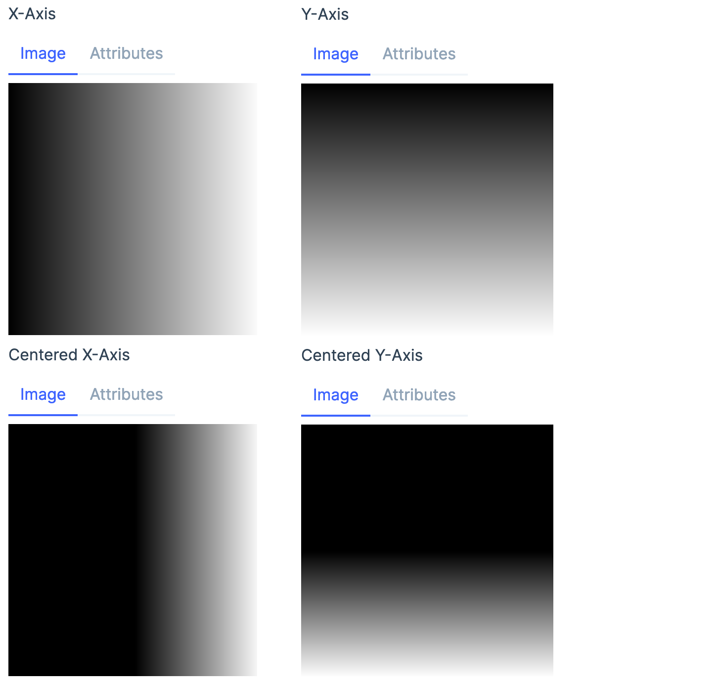
Now that we have an image, we can see how it looks in polar plane
# convert band format to complex number format.
# we specify that read 2 bands to form a single complx band.
# x axis becomes the real part of the complex number
# y axis becomes the Imaginary part of the complex number
complex_xy = Operation.copy!(xy, format: :VIPS_FORMAT_COMPLEX, bands: 1)

# change complex number plane to polar plane.
# vips reads complex number and converts that to polar value for all pixels.
# real part will be distance from the origin
# imaginary part will be the angle in degree
polar_xy = Operation.complex!(complex_xy, :VIPS_OPERATION_COMPLEX_POLAR)

# convert the complex number back to 2 band float image.
# x axis is the real part of the complex number
# y asix is the imaginary part of the complex number
xy = Operation.copy!(polar_xy, format: :VIPS_FORMAT_FLOAT, bands: 2)

# angle will be in degree (from 0 to 360), scale it back to 255
xy = xy * [1, height / 360]

Kino.Layout.grid([Kino.Text.new("X-Axis"), Kino.Text.new("Y-Axis"), xy[0], xy[1]], columns: 2)
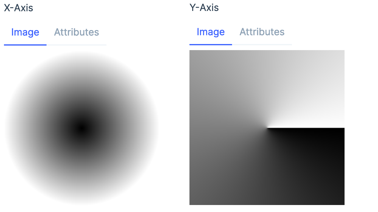
As you can see x axis is the real part of the complex number, which is distance from the origin and Y axis is the imaginary part of the complex number which is the angle.
This is much easier to understand if we draw few line on the input image. and see how it changes in the polar plane
defmodule ComplexOps do
  def to_polar(img, background \\ [0, 0, 0]) do
    %{width: width, height: height} = Image.headers(img)
    xy = Operation.xyz!(width, height)
    xy = xy - [width / 2, height / 2]

    scale = min(height, width) / width
    xy = xy * 2 / scale

    xy =
      xy
      |> Operation.copy!(format: :VIPS_FORMAT_COMPLEX, bands: 1)
      |> Operation.complex!(:VIPS_OPERATION_COMPLEX_POLAR)
      |> Operation.copy!(format: :VIPS_FORMAT_FLOAT, bands: 2)

    xy = xy * [1, height / 360]

    # mapim takes an input and a `map` and generates an output image
    # where input image pixels are moved based on map.
    #
    # [new_x, new_y] = map[x, y]
    # out[x, y] = img[new_x, new_y]
    #
    # mapim is to roate, displace, distort, any type of spatial operations.
    # where the pixel value (color) remain same but the position is changed.
    Operation.mapim!(img, xy, background: background)
  end
end

x_line = Operation.black!(10, height) + 255
y_line = Operation.black!(width, 10) + 125

# create a black image and draw 2 lines
# an x axis at 50
# a y axis at 50
img =
  Operation.black!(width, height)
  |> Operation.insert!(x_line, 50, 0)
  |> Operation.insert!(y_line, 0, 50)

# convert img to polar
out = ComplexOps.to_polar(img)

Kino.Layout.grid([Kino.Text.new("Input"), Kino.Text.new("Output"), img, out], columns: 2)
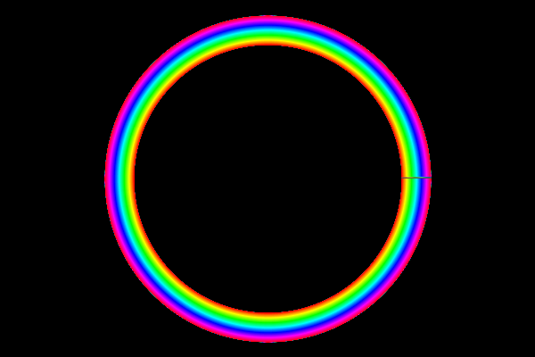
A line on the x axis becomes a circle on the polar plane and a line on the y axis becomes a line from the origin.
So to draw a rainbow circle we just need to draw a rainbow line on the x axis and convert that to polar plane!
rainbow_colors
|> Operation.resize!(100 / 255, vscale: 400)
|> Operation.embed!(150, 0, 600, 400)
# wrap moves the image to origin
|> Operation.wrap!()
|> ComplexOps.to_polar()
All that is left now is to make few final adjustments to make it pretty
# create colors from violet to red instead of red to red
{:ok, mat} = Image.new_matrix_from_array(4, 2, [[0, 220, 255, 255], [255, 0, 255, 255]])

rainbow_colors =
  Operation.copy!(Operation.buildlut!(mat),
    band_format: :VIPS_FORMAT_UCHAR,
    interpretation: :VIPS_INTERPRETATION_HSV
  )

sky_color = [135, 100, 255]

rainbow_colors
|> Operation.resize!(100 / 255, vscale: 500)
|> Operation.embed!(50, 0, 500, 500, background: sky_color)
|> Operation.wrap!()
|> ComplexOps.to_polar(sky_color)
# take only top half of the image
|> Operation.copy!(height: 250, width: 500)