Document Auto Rotation
This is blog version of the Livebook. You can try interactive nootbook here
![]()
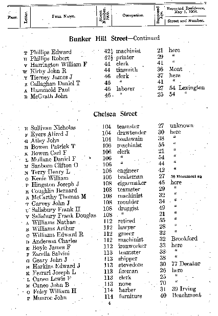
In this post, we’ll explore how to correct text image rotation using image processing methods such as Fourier Transformation, complex planes, and basic arithmetic operations.
This tutorial is heavily based on libvips blog post and a Stack Overflow answer.
Setup
alias Vix.Vips.Image
alias Vix.Vips.Operation

# import convenience math operators `+`, `-`, `*` etc.
use Vix.Operator

{:ok, doc} = Image.new_from_file("test-image.png")

# convert 4 channel/band PNG image to black & white
doc = Operation.colourspace!(img, :VIPS_INTERPRETATION_B_W)

# img[1] is alpha band, skip that
doc = img[0]
Fourier Transformation
An image can be expressed as sum of sine and cosine waves of varying magnitude, frequency and phase. Fourier Transform is an operation which breaks down an image into its sine and cosine components, which is crucial for many image processing tasks.
There are lot of resources online on this topic, I found this and this useful get started.
Libvips provides functions like fwfft
for Forward Fourier Transform and
invfft
for Inverse Fourier Transform.
Fwfft Operation
When we perform fwfft operation on an image, we get a complex band format where the real part represents the wave amplitude and the imaginary part represents the wave phase. Position of the value is the frequency.
However, this complex format isn’t directly visible, so we need to convert it to a format that can be displayed. We do that by converting the single complex band to two bands of type float, one for real part and another for imaginary part. And then we can warp the image to center, scale values to make them more visible.
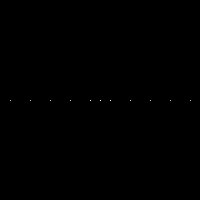
white = Operation.black!(10, 200) + 255
line_img = Operation.embed!(white, 45, 0, 200, 200)

# take fourier transform of the input image
fourier_transform = Operation.fwfft!(line_img)
| line_img | fourier_transform | |
|---|---|---|
| Image |  |
 |
| Format | :VIPS_FORMAT_FLOAT |
:VIPS_FORMAT_DPCOMPLEX |
| Bands | 1 |
1 |
# convert complex number to 2 band double format
fourier_transform = Operation.copy!(fourier_transform, format: :VIPS_FORMAT_DOUBLE, bands: 2)

# do logarithm scaling for the image so that points visible
# and move the origin of the image to center
scaled_fourier_transform =
  fourier_transform
  |> Operation.scale!(log: true)
  |> Operation.wrap!()

# separate amplitude and phase channels/bands
amplitude = scaled_fourier_transform[0]
phase = scaled_fourier_transform[1]
| amplitude | phase |
|---|---|
 |
 |
Libvips simplifies this process of conversion by offering function
spectrum, which compute the Fourier Transform, extract the
amplitude, scale it logarithmically, and wrap it around the origin for
visualization.
spectrum = Operation.spectrum!(line_img)
| spectrum |
|---|
 |
Let’s display fourier transform for few synthetic sample images to get the intuition behind the operation
lines_count = 10

# lets create images which black and white lines
width = trunc(100 / lines_count)
black_line = Operation.black!(width, 200)

# 10 lines B&W lines
lines =
  [black_line, Operation.invert!(black_line)]
  |> List.duplicate(lines_count)
  |> List.flatten()

vert_lines = Operation.arrayjoin!(lines, across: length(lines))
horz_lines = Operation.rot!(vert_lines, :VIPS_ANGLE_D90)
vert_horz_lines = vert_lines + horz_lines
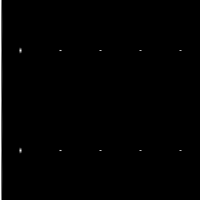
| img | Operation.spectrum!(img) | |
|---|---|---|
| vert_lines |  |
 |
| horz_lines |  |
 |
| vert_horz_lines |  |
 |
By observing the Fourier Transform outputs of various sample images, we notice a consistent pattern: vertical lines in the input image produce horizontal lines in the Fourier Transform, and vice versa. This pattern remains unchanged even when the number of lines in the input image is altered.
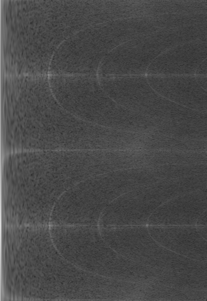
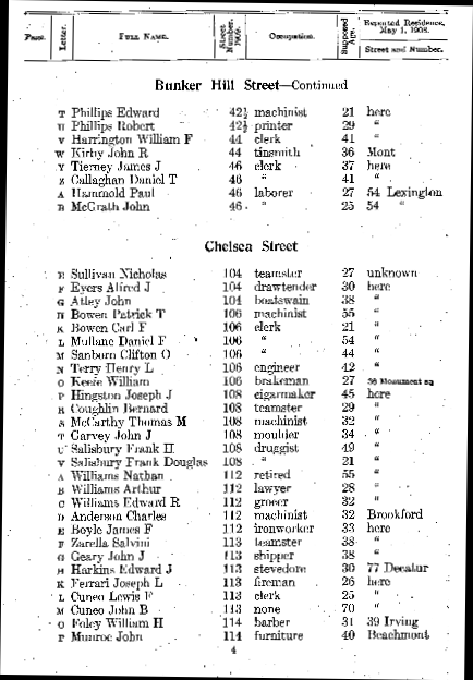
When we apply Fourier Transform to an ideal text image, we expect to see vertical and/or horizontal lines precisely at 0, 90, 180, and 270-degree angles. This alignment occurs because characters and lines in a text document are typically parallel or perpendicular to each other. If the document is rotated by some angle, this misalignment will be reflected in the Fourier Transform.
| doc | Operation.spectrum!(doc) |
|---|---|
|
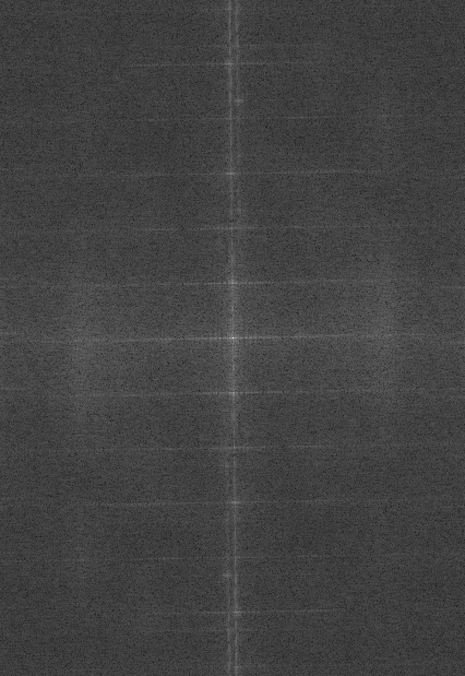 |
As observed, we can detect a slight deviation in the vertical and horizontal lines within the Fourier Transform. Now, our next step is to determine the angle of this deviation.
Finding the Rotation Angle
As previously mentioned, the output of the Fourier Transform is in a complex band format. This format consists of a real part, representing the amplitude (visible lines), and an imaginary part, representing the phase.
To interpret these complex numbers on a 2D plane, we have two options: Cartesian (rectangular) coordinates and Polar coordinates.
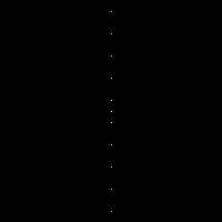
Libvips provides functions to convert between Cartesian and Polar coordinates. When converting from Cartesian to Polar coordinates, vertical lines in the image transform into circles, while horizontal lines become arcs or segments. Importantly, in this conversion, the radius of the circle corresponds to the x-axis, and the angle of rotation corresponds to the y-axis. See Creating Rainbow post for more information on this.
And we can do inverse operation as well. We can convert an image from the Polar plane to the Cartesian plane. In this transformation, the circular shapes in the Polar plane become vertical lines, and the arcs or segments become horizontal lines. Most significantly, the radius in the Polar plane translates to the x-axis, while the angle corresponds to the y-axis in the Cartesian plane. This transformation allows us to interpret complex numbers represented in Polar coordinates as points in the Cartesian plane, with the radius dictating the position along the x-axis and the angle determining the position along the y-axis.
defmodule ComplexOps do
  def to_cartesian(img, background \\ [0, 0, 0]) do
    %{width: width, height: height} = Image.headers(img)
    xy = Operation.xyz!(width, height)

    # normalize the y-axis to be between 0 and 360
    xy = xy * [1, 360 / height]

    xy =
      xy
      # read values as complex numbers
      |> Operation.copy!(format: :VIPS_FORMAT_COMPLEX, bands: 1)
      # convert from polar to Cartesian plane
      |> Operation.complex!(:VIPS_OPERATION_COMPLEX_RECT)
      # and convert back to float
      |> Operation.copy!(format: :VIPS_FORMAT_FLOAT, bands: 2)

    scale = min(width, height) / width
    xy = xy * (scale / 2)
    xy = xy + [width / 2, height / 2]

    # mapim takes an input and a `map` and generates an output image
    # where input image pixels are moved based on map.
    #
    # [new_x, new_y] = map[x, y]
    # out[x, y] = img[new_x, new_y]
    #
    # mapim is to rotate, displace, distort, any type of spatial operations.
    # where the pixel value (color) remain same but the position is changed.
    Operation.mapim!(img, xy, background: background)
  end
end


Enum.flat_map([vert_lines, horz_lines, vert_horz_lines], fn sample ->
  polar = Operation.spectrum!(sample)
  cartesian = ComplexOps.to_cartesian(polar)
  [sample, polar, cartesian]
end)
| sample | polar | cartesian | |
|---|---|---|---|
| vert_lines | |
|
 |
| horz_lines | |
|
 |
| vert_horz_lines | |
|
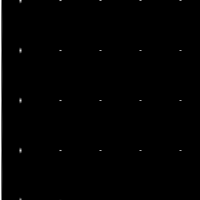 |
For the input document
| polar | cartesian |
|---|---|
|
 |
Now, the remaining task is to identify the row with the maximum value
in the Cartesian plane. The row number associated with this maximum
value corresponds to the angle of rotation we’re seeking. Libvips
simplifies this process with its project function. This function
calculates the row-wise and column-wise sums of the image and returns
them as an image. Then, we can use the max function to find the
maximum value and its position within the image.
defmodule Angle do
  def find(cartesian) do
    # find the row wise and column wise sum
    # returns 2 images with respective column/row sum
    {_columns, rows} = Operation.project!(cartesian)

    # find position of the row with maximum value
    {_, %{y: y_pos}} = Operation.max!(rows)

    # convert the y position back to angle.
    y_pos / Image.height(rows) * 360
  end
end

[vert_lines, horz_lines, vert_horz_lines]
|> Enum.flat_map(fn sample ->
  ft = Operation.spectrum!(sample)
  cartesian = ComplexOps.to_cartesian(ft)

  angle = Angle.find(cartesian)
  [sample, ft, cartesian, angle]
end)
| sample | ft | cartesian | angle | |
|---|---|---|---|---|
| Vertical | |
|
|
0.0 |
| Horizontal | |
|
|
90.0 |
| Grid | |
|
|
0.0 |
If there are multiple rows maximum values then it picks one of them.
fourier_transform = Operation.spectrum!(img)
cartesian = ComplexOps.to_cartesian(fourier_transform)

angle = Utils.find_angle(cartesian)

# since we know that angle can only be parallel or perpendicular
# can take mod of 90
angle = angle - trunc(angle / 90) * 90
89.27302100161552
Correcting the Rotation
With the rotation angle determined, we can now apply it to the original document image to correct its rotation. This involves calculating the difference between the determined angle and 90 degrees (since text documents are typically aligned parallel or perpendicular to the axes) and then rotating the image accordingly.
diff = 90 - angle
corrected = Operation.rotate!(doc, diff)
| doc | corrected |
|---|---|
|
 |